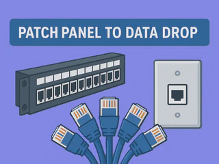
Patch Panel to Data Drop: A Field Tech Guide
Introduction
Setting up the backbone of a building’s network infrastructure does not end once the cables are pulled through walls and ceilings, it is just the beginning.
After the physical cabling is in place, the real craft lies in how those cables are terminated, organized, and tested. This stage determines whether the network will perform reliably for years to come or suffer from chronic connectivity issues and costly downtime.
As a field technician, you’re the last line of defense between a well-designed cabling plan and a fully operational network. Every connector you punch down, every patch panel you label, and every test report you certify contributes to the system’s integrity. Proper terminations ensure strong signal transmission and minimize interference, while thorough testing verifies that the installation meets or exceeds performance standards like TIA/EIA-568[1] or ISO/IEC 11801[2].
In this article, we’ll walk through what it takes to bring a structured cabling system online after the runs have been completed. We’ll cover the tools, techniques, and best practices involved in:
- Terminating twisted-pair cables into jacks and patch panels
- Maintaining pair integrity and minimizing crosstalk
- Labeling and organizing terminations for long-term maintenance
- Testing cable performance with certifiers and troubleshooters
- Documenting results to ensure compliance and future serviceability
Whether you’re wiring a small office or a multi-floor enterprise facility, mastering proper termination and testing practices is what separates a good installation from a great one. Once the drywall is closed and the network goes live, your workmanship becomes the unseen backbone that keeps every switch, server, and workstation connected.
History
Ethernet was developed in 1973 at Xerox’s Palo Alto Research Center (PARC) by Robert Metcalfe and his team. Their goal was to create a simple way for computers to share data over a common communication line. The first system used coaxial cable to transmit digital signals between multiple devices.[3]
In 1980, Xerox partnered with Digital Equipment Corporation (DEC) and Intel to publish the DIX Ethernet Specification, the first open networking standard. This led to the IEEE 802.3 standard in 1983, which still defines Ethernet operation today.[4]
Early Ethernet systems used thick coaxial cable (10BASE5, “Thicknet”) and later thinner coaxial cable (10BASE2, “Thinnet”). In the late 1980s, 10BASE-T introduced twisted-pair cabling, allowing networks to use a star topology with hubs, switches, and patch panels; the foundation of modern structured cabling systems.[5]
Since then, Ethernet has advanced from 10 Mbps to multi-gigabit and even terabit-speed networks, but its basic function remains the same: fast, reliable, and scalable wired communication.[6]
Cat Cable Types
Ethernet cables are rated by category (“Cat”), which defines their performance in terms of bandwidth, data speed, and electrical characteristics. Each newer category improves upon the previous one with tighter twists, better insulation, and reduced interference.
Cables also differ by construction and shielding:
Solid conductor: Better for permanent in-wall or horizontal runs (less signal loss over distance).
Stranded conductor: More flexible; used for patch cords and movable connections.
Shielding types:
UTP (Unshielded Twisted Pair) - most common for general LAN use.
STP/FTP (Shielded/Foiled Twisted Pair) - used in high-interference environments or when required by spec. [7]

Comparison of Unshielded Twisted Pair (UTP) and Shielded Twisted Pair (STP) cable construction. Image courtesy of Tripp Lite by Eaton. Source: Tripp Lite - UTP & STP. Referenced in [7].
| Category | Max Speed / Distance | Bandwidth | Shielding Options | Conductor Type | Common Uses & Notes |
|---|---|---|---|---|---|
| Cat3 | 10 Mbps @ 100 m | 16 MHz | UTP | Solid / Stranded | Legacy cable used for early Ethernet and still common in telephony and fax lines. Often found in older buildings. |
| Cat5 | 100 Mbps @ 100 m | 100 MHz | UTP / FTP | Solid / Stranded | Early standard for Fast Ethernet (10/100BASE-T). Rarely installed new, but still operational in older networks. |
| Cat5e | 1 Gbps @ 100 m | 100 MHz | UTP / STP / FTP | Solid / Stranded | “Enhanced” Cat5 with better twist ratios and reduced crosstalk. Standard for many small office LANs. |
| Cat6 | 1 Gbps @ 100 m / 10 Gbps @ ≤55 m | 250 MHz | UTP / STP / F/UTP | Solid / Stranded | Thicker conductors and separator reduce interference. Good balance of cost and performance. |
| Cat6A | 10 Gbps @ 100 m | 500 MHz | UTP / STP / F/FTP | Solid / Stranded | “Augmented” Cat6 with tighter twists and better shielding. Standard in modern enterprise installations. |
| Cat7 | 10 Gbps @ 100 m | 600 MHz | S/FTP (individually shielded pairs + overall braid) | Solid | High-end shielded cable used in data centers and EMI-heavy environments. Uses GG45 or TERA connectors. |
| Cat7A | 10-40 Gbps @ 50 m | 1000 MHz | S/FTP | Solid | Improved shielding for 40 Gbps short-run applications; mostly European standard. |
| Cat8 | 25-40 Gbps @ ≤30 m | 2000 MHz | S/FTP | Solid | Designed for data centers and short-distance, high-speed interconnects. Not for general office use. |
After the cable runs are complete and the correct type has been installed, the next step is termination and testing. Proper terminations ensure signal integrity, and testing confirms that each run meets standard performance requirements. The following sections outline how to prepare, terminate, and certify network cabling correctly.
Choosing the Right Rack
Selecting the correct rack is critical before mounting patch panels, switches, or servers. The rack must provide enough space, depth, and airflow for all current and planned equipment. A properly sized rack also simplifies cable management and leaves room for future expansion.
Rack Units (U):
Standard racks are measured in “U,” where 1U = 1.75 inches of vertical space. Most network devices such as switches, routers, and patch panels are designed in 1U form factors for modular stacking.[8]
Servers, particularly those used for storage or virtualization, are typically 2U to 4U or even larger depending on hardware density and cooling needs.
When planning rack space, account for future expansion and allow clearance above and below each device for cable management. Calculate total space for patch panels, switches, PDUs, and servers, then reserve about 25% free space for growth. Tools like draw.io, Cisco Packet Tracer, or equivalent software can help visualize rack layouts and interconnections before installation, or better yet, sketch it out in your field notebook, where referencing, adjustments, and learning work best.
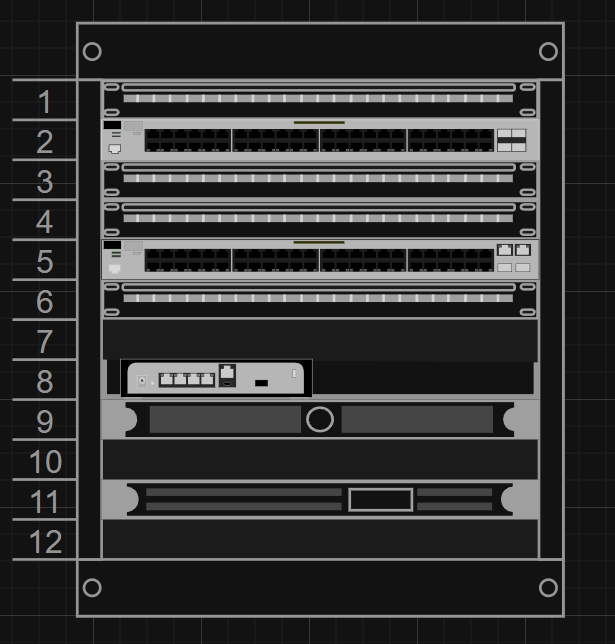
Custom 12U rack layout diagram created using Draw.io. Referenced in [9].
Small network closets often use 12U-24U wall-mount racks, which range from basic open-frame designs to fully enclosed, climate-controlled models, like the ones shown below.
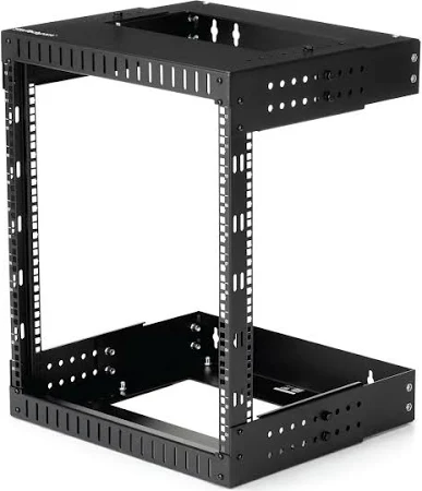
12U Open Frame Server Rack, heavy-duty wall-mount network rack. Image courtesy of StarTech.com. Referenced in [10].

12U Wall Mount Rack with thermostat, cooling fans, and lockable glass door. Product image courtesy of TecMojo. Referenced in [11].
Larger telecom or server rooms typically use 42U floor racks to accommodate full-size switches and servers. This article focuses on smaller wall-mount racks, but the setup principles and organization practices apply to both.
Rack Specifications
Depth:
18-24" → For patch panels and compact switches
30" → Fits most standard switches
36-48" → Needed for servers and chassis-based equipment
Always confirm device depth before purchase.[12]
Width:
Standard 19" mounting rails fit most network gear. Wider 23" racks allow easier cable routing but may need adapters.
Ventilation and Airflow:
Maintain front and rear clearance. Avoid overcrowding. For enclosed racks, use fan kits or perforated doors.
Cable Management:
Choose racks with vertical and horizontal managers, brush panels, and side channels. Keep network and power cabling separated.
Mounting and Grounding:
Secure the rack to wall or floor and bond it to the building ground this is essential for shielded cabling and metal enclosures.
💡 Field Tip:
When planning rack layout, mock it up on paper or tape it out on the floor before mounting. This prevents clearance issues with door swing, PDU access, or server slide rails. Always verify power and ventilation before you start terminating.
Tools & Materials
A clean termination doesn’t require a full toolbox, just the right few tools used correctly. The key is control, accuracy, and double-checking every cut or punch to avoid hidden nicks that can fail a test later. Even professional cable strippers can nick conductors if you rush or apply too much pressure.
Essential Tools
- Punch-down tool - A reliable, spring-loaded 110-style punch-down tool for seating conductors in jacks and patch panels. Use consistent pressure and check every termination for full contact.
- Titanium electrician’s scissors - Sharp, durable, and versatile. Use them for cutting jacket, trimming pairs, and general prep. A good pair can replace separate cutters and strippers when used carefully.
- RJ45 crimp tool - For attaching RJ45 connectors. Check alignment before crimping and verify each pin seats evenly.
- Klein Tools LAN Scout Jr. 2 Cable Tester - Quick continuity and pinout verification tool for confirming correct pair order and connection integrity before final certification.
- Label printer with extra rolls - Label both ends of every cable, patch panel port, and faceplate. Proper labeling saves time during testing and future maintenance.
- Sharpie or permanent marker - Reliable backup for quick notes on any surface or temporary labeling when a printer isn’t available.
Essential Network Hardware/Materials
- Patch panels (Keystone 1U recommended) - Primary termination point for horizontal cabling. Organizes cable runs and provides easy patching access to switches or distribution hardware.
- Keystone jacks - Termination points for data drops and patch panels. Always match your cable category (Cat5e, Cat6, Cat6A, etc.); higher-rated jacks are backward-compatible. Many CableMatters jack kits include a keystone jack holder for easier punchdowns.
- Faceplates - Mount keystone jacks at workstations or crucial locations for a clean, finished appearance. Use multi-port plates where needed for flexibility.
- Velcro straps or cable organizers - Manage cable bundles without compressing or damaging jackets. Maintain bend radius and airflow in racks.
- Grounding hardware - Required for shielded cabling and metal patch panels to prevent signal interference and meet safety codes.
- RJ45 connectors - Shielded or unshielded to match your cable and Cat rating. Pass-through style speeds assembly for custom patch cords and field-terminated device runs (e.g., IoT/PoE cameras). Not required for standard permanent links that terminate on jacks/patch panels.
- Jack and faceplate blanks - Used to fill unused ports in patch panels or wall plates. Keeps dust out, maintains a clean appearance, and helps with proper airflow and pressure balance in racks or enclosures.
- Plywood backboard and mounting screws (drywall installation) - Install a ¾-inch fire-rated plywood backboard behind the rack location when mounting on drywall or other non-load-bearing surfaces. This creates a solid surface for anchors, distributes the rack’s weight, and allows easy reconfiguration later. Secure the backboard with #12 wood screws or 3/8″ lag bolts into studs, using washers for even load distribution.
Alternative Tools (Optional but Useful)
For higher-volume or precision work, these can improve efficiency:
- Adjustable cable stripper with depth control
- Cable cutter for thicker Cat6A or shielded cable
- Tone generator and probe for tracing unidentified cables
- Cable certifier for full TIA/EIA or ISO performance verification
- Needle-nose pliers for manipulating wires in tight spaces
Mounting the Rack
Wall-mount racks are typically used for 12U-24U network installations. These follow the EIA-310 standard, the industry specification that defines the 19-inch rack width, 1U height spacing (1.75 inches), and mounting-hole geometry. Adhering to EIA-310 ensures compatibility between racks, patch panels, switches, and servers from all major manufacturers. Properly mounting the rack to spec maintains safety, stability, and alignment with your cable routes and entry points.[13]
1. Location
- Align the rack with where your cable bundles enter (from ceiling, conduit, or wall penetration). This minimizes strain and prevents sharp bends at the patch panel.
- Mount the rack on a solid surface; ideally a concrete wall or plywood-backed stud wall.
- Ensure clearance for door swing, patch cords, and access above and below.
- Confirm power outlet access and equipment ventilation.
- Maintain comfortable working height:
- For 12U racks, the top should be around 6 ft off the floor.
- For heavier 24U enclosures, mount slightly lower for weight balance.
2. Measure Twice - Mark and Level
- Use the rack’s mounting template or bracket to mark hole positions.
- Check alignment with cable routes; cable bundles should feed directly into the top or rear of the rack without needing hard bends.
- Verify with a level before drilling; even minor misalignment will affect patch panel fit later.
3. Drill and Anchor Once
Select anchors appropriate for the wall type:
Concrete or block: use expansion or wedge anchors.
Wood studs: use 5/16"-3/8" lag bolts centered on each stud.
Pre-drill to prevent cracking or splitting.
Ensure anchor depth and spacing match the rack’s weight rating (most 12U-24U racks handle 100-200 lbs).
4. Mount and Secure
- Have an assistant help you level the rack.
- Hang the top bolts loosely first, then swing and align the rack before tightening.
- Secure bottom bolts and confirm that the rack sits flush to the wall and opens/closes freely if hinged.
5. Ground and Test
- Connect the rack’s grounding lug to the building ground using 12-14 AWG stranded copper.
- Verify continuity if using shielded cabling or metal patch panels.
- Perform a light tug test to confirm the frame is solid before loading equipment.
Video courtesy of CableSupply.com, used under YouTube’s standard embedding license. Referenced in [14].
Terminating into Jacks and Keystones
The goal is clean IDC terminations that pass certification and survive moves, adds, and changes.
Step-by-step
1. Prep
- Measure slack; leave a service loop (~0.5-1 m in closet, ~15-30 cm at outlet).
- Score the jacket (don’t cut through), bend/twist to peel.
- Slide a short jacket sleeve over one conductor and run it down the pair to untwist without nicking insulation.
2. Pair management
- Keep each pair twisted to within ≤13 mm (½") of the IDC slots.
- Do not split pairs; route as pairs to the posts.
3. Seat & punch (110/Krone as required)
- Place wires per T568A or T568B (pick one site-wide and stick to it).
- Use a spring-loaded punch-down, blade oriented to trim the scrap on the waste side.
- Full seat = conductor bottomed in IDC, clean trim, no copper exposed.
4. Strain relief & dress
- Snap on the jack’s strain-relief cap/cable clamp so the jacket (not the conductors) is retained.
- Maintain bend radius (≥4× cable OD for UTP; follow manufacturer spec for F/UTP, S/FTP).
- Label the jack and record on your choice of documentation network map or spreadsheet.
5. Verify
- Use the LAN Scout Jr. 2 (or equivalent) at each connection for pinout/continuity before closing the plate or dressing the panel.
T568A / T568B Color Codes (Jack View)
| Pin | Pair | T568A | T568B |
|---|---|---|---|
| 1 | 2 | White/Green | White/Orange |
| 2 | 2 | Green | Orange |
| 3 | 3 | White/Orange | White/Green |
| 4 | 1 | Blue | Blue |
| 5 | 1 | White/Blue | White/Blue |
| 6 | 3 | Orange | Green |
| 7 | 4 | White/Brown | White/Brown |
| 8 | 4 | Brown | Brown |
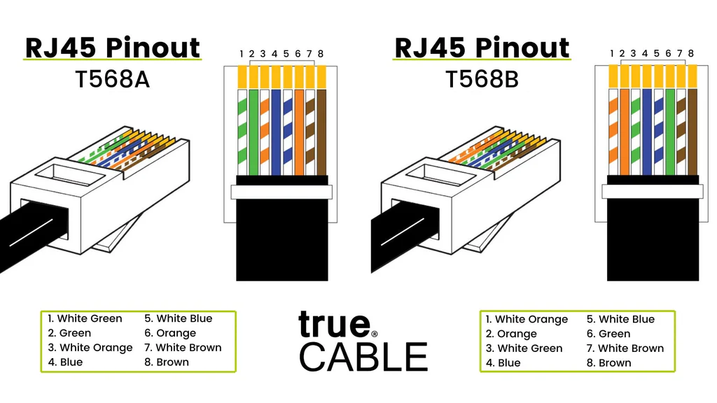
Comparison of T568A and T568B Ethernet wiring standards, showing pair and pin alignment. Image courtesy of trueCABLE. Source: trueCABLE - T568A vs T568B. Referenced in [15].
Notes
- Choose A or B once per site. B is most common in the U.S., and it’s highly recommended to stick to local standards, especially for non-residential setups, to make future maintenance easier; never mix standards within a channel.
- For shielded cable, bond the jack/patch panel per the hardware instructions.
💡 Field Tip:
Scoring the jacket: Lightly score the outer jacket with your scissors; just enough to mark it. Don’t cut through.
Bend and twist to remove: Bend the cable at the score line and twist slightly to split the jacket, then peel it off cleanly.
Untwist pairs safely: Use the piece of removed jacket as a sleeve. Insert one wire into it and slide down the pair; this straightens and separates without damaging the insulation or tearing up your fingers.
Inspect every run: Before punching down, look closely for conductor nicks or insulation cuts. Even tiny damage can cause impedance mismatches or failures during certification.
Jacket retention: The clamp/boot should grip the cable jacket, not the pairs.
No over-cinching: Use Velcro, not zip ties, near terminations.
Bend radius: Maintain spec; avoid hard bends right off the jack or panel.
Re-inspect: Look for nicks on conductors; nicks happen even with strippers; replace the segment if found.
Testing & Certification
Once all terminations are complete, every cable must be tested for continuity, correct pinout, and performance.
1. Basic Testing (Verification): Use a handheld tester like the Klein LAN Scout Jr. 2 to confirm:
- All 8 conductors are present and correctly ordered (T568A or T568B).
- No opens, shorts, or split pairs.
- Link LEDs confirm connectivity end-to-end.
This level of testing verifies that every termination is wired correctly and that each drop is live. This is ideal for small jobs, home networks, or quick post-termination checks before labeling.
⚠️ Continuity testers cannot detect issues like crosstalk, impedance mismatches, or minor conductor damage that can cause data errors under load.
2. Certification (Performance Testing)
For new installations, final inspections, when providing deliverables to the customer, or warranty documentation, full performance certification is necessary.[16]
Certification testers, such as the Fluke DSX-5000/8000, NetAlly LinkIQ, or Ideal LanTEK IV; measure and record key electrical parameters including:
NEXT / FEXT (Near-End and Far-End Crosstalk):
Interference caused when the signal on one twisted pair induces unwanted noise on another. Excessive crosstalk leads to data errors and lost throughput.Return Loss:
Signal reflections caused by impedance mismatches, often from kinks, nicks, or inconsistent terminations, reduce transmission quality. [17]Propagation Delay / Skew:
The time it takes a signal to travel through each pair, and the difference between them. High skew can break gigabit-speed synchronization.Length, Resistance, and Wiremap:
Confirms each run’s physical integrity, measuring total length, conductor resistance, and proper pin-to-pin wiring.
These measurements verify that the cable meets its rated performance (Cat 5e, 6, 6A) under the TIA/EIA or ISO standards.
Certification testing is required when:
- You’re delivering a project under warranty compliance (Leviton, Panduit, Belden, etc.).
- The installation is for commercial, enterprise, or government environments.
- The network supports 10 GbE or higher, PoE++, or long-distance structured cabling.
3. Strain and Visual Inspection
Before labeling is complete, verify:
- No conductor nicks or insulation cuts
- Jackets are retained in clamps
- Bend radius and dressing are clean
💡 Field Tip:
Always test before labeling and dressing; chasing down a mislabeled or dead run after the fact costs more time than a full retest.
Common Mistakes and Fixes
Even small errors in cable prep or termination can cause major network issues later.
Miswiring (Wrong Pinout):
Mixing T568A and T568B standards on opposite ends results in crossover or no link at all. Always double-check color order before punching down.- Fix: Re-terminate both ends using the same standard (T568A or T568B). Verify with a tester before closing up the panel or faceplate.
Untwisting Pairs Too Far:
Untwisting more than half an inch near the termination increases crosstalk and reduces performance; especially on Cat6 and higher cables.- Fix: Trim back and re-punch the pair with less than ½" untwist. Maintain the twist right up to the IDC slot.
Cable Kinks or Sharp Bends:
Tight bends exceed the minimum bend radius, causing impedance mismatches or physical conductor damage. Follow the manufacturer’s bend-radius spec (usually 4× the cable diameter).- Fix: If the conductor jacket is visibly creased or flattened, re-pull that section. Even minor kinks can fail certification later.
Poor or Missing Labeling:
Unlabeled cables waste hours during troubleshooting. Label both ends immediately after verification and include port numbers and destinations.- Fix: Label as soon as each drop tests good. Use a clear numbering scheme (e.g., TR-1-01 to TR-1-24) and mirror it at both ends.
Improper Jacket Stripping:
Cutting too deep can nick the conductor insulation. Score lightly and bend the jacket to break it cleanly (see Field Tip in Tools section).- Fix: Cut back to clean copper and re-terminate. If damage is near the jack, replace the module entirely.
No Strain Relief or Improper Clamping:
Leaving too much slack or skipping strain relief at jacks and patch panels leads to intermittent disconnects over time.- Fix: Inspect punch-downs and crimps for loose pins. Re-seat connections and retest with a certified verifier before closing up.
Skipping Final Tests:
Always verify continuity and polarity before labeling. For client jobs, perform full certification testing to document compliance.- Fix: Do it right and take pride in your work, quality is something you should always strive for.
Fun Facts
- T568A and T568B wiring standards only differ by two swapped pairs (Pair 2 Orange/White-Orange and Pair 3 Green/White-Green), and both perform the same if used consistently.
- A single kink in a Cat6A cable can lead to significant performance degradation.[18]
- Many enterprise warranties require Fluke certification reports before they’ll honor product support. [16]
- Patch panels don’t improve performance; they exist purely for organization, flexibility, and future serviceability.
- The typical Cat6A solid copper cable has a bend radius of about 1 inch; any tighter and signal reflections increase.
- Other terms for the rack room are MDF/IDF, from legacy telephony (“Main” and “Intermediate Distribution Frames”).
- Even though fiber is becoming common, Ethernet over copper still handles more than 70% of local network links worldwide.
Conclusion
Every cable you terminate and every label you print becomes part of a system that someone will rely on, probably years after you have left the site. The difference between a good technician and a great one isn’t speed; it’s attention to detail and consistency. By following standards like TIA/EIA-568 and ISO/IEC 11801, testing every link, and keeping your work organized, you’re not just finishing a job, you’re building trust in the network and in your craft.
Disclosure: Some product links on this page are affiliate links. If you purchase through them, I may earn a small commission at no additional cost to you.
References
[1] Telecommunications Industry Association (TIA). ANSI/TIA-568.0-E: Commercial Building Telecommunications Cabling Standard.
2022.
https://store.accuristech.com/tia/standards/tia-tia-568-0-e?product_id=2594225
[2] International Organization for Standardization. ISO/IEC 11801:2017 - Information Technology - Generic Cabling for Customer Premises.
2017.
https://www.iso.org/standard/66182.html
[3] Ethernet and Robert Metcalfe at Xerox PARC (1971-1975).
History of Computer Communications Project.
https://historyofcomputercommunications.info/section/8.7/Ethernet-and-Robert-Metcalfe-and-Xerox-PARC-1971-1975/
[4] Ethernet Network - Overview and Principles.
ScienceDirect Topics.
https://www.sciencedirect.com/topics/computer-science/ethernet-network
[5] Thicknet vs. Thinnet - Key Differences.
RF Wireless World.
https://www.rfwireless-world.com/terminology/thicknet-vs-thinnet
[6] Approved Networks. A New Internet Speed Record.
2024.
https://approvednetworks.com/blog/a-new-internet-speed-record/
[7] Ethernet Cable Types and Their Uses.
Tripp Lite by Eaton.
https://tripplite.eaton.com/products/ethernet-cable-types
[8] Server Rack Sizes Explained: 1U, 2U, 3U, 4U.
C&T Solution.
https://www.candtsolution.com/news_events-detail/server-rack-sizes-1u-2u-3u-4u-explained/
[9] Draw.io Blog - Rack Diagrams and Network Layouts.
2024.
https://www.drawio.com/blog/rack-diagrams
[10] StarTech.com. 12U Open Frame Server Rack - Heavy-Duty Wall Mount Network Rack.
Product listing.
https://amzn.to/47oSFD6
[11] TecMojo. 12U Wall Mount Rack with Thermostat, Cooling Fans, and Lockable Glass Door.
Product listing.
https://amzn.to/4oIepQ0
[12] Server Rack Sizes: Inside vs. Outside Rack Depth.
PhoenixNAP Data Center Blog.
https://phoenixnap.com/blog/server-rack-sizes
[13] Electronic Components Industry Association (ECIA). EIA-310-E Standard - Cabinets, Racks, Panels, and Associated Equipment.
2005.
https://store.accuristech.com/standards/ecia-eia-eca-310-e?product_id=2585295
[14] CableSupply.com. Mounting a 12U Wall Rack.
YouTube video, 2018.
https://www.youtube.com/watch?v=qqPJvr1ic3Q
[15] trueCABLE. T568A vs T568B Wiring Diagram.
2020.
https://www.truecable.com/blogs/cable-academy/t568a-vs-t568b
[16] Fluke Networks. ROI of Certification Testing and Manufacturer Warranties.
Fluke Networks Blog.
https://www.flukenetworks.com/blog/cabling-chronicles/roi-of-certification-testing#:~:text=Manufacturers%20don't%20hand%20out,application%20warranty%2C%E2%80%9D%20asserts%20Valentukonis.
[17] How Cable Bend Radius Affects Performance.
Cat6A Cabling News.
https://www.cat6acabling.com/news/how-cable-bend-radius-affects-performance-and-85184206.html
[18] JabberComm, Inc. The Science Behind Electrons in Cat6 Cables and the Importance of Neat, Kink-Free Cabling.
September 20, 2024.
https://www.jabbercomm.com/blog/the-science-behind-electrons-in-cat6-cables-and-the-importance-of-neat-kink-free-cabling/
Disclaimer: AI tools were used in the development of this article to assist with drafting and refinement. All content has been reviewed and approved for accuracy.